Posted on Oktober 4, 2012 by ivanemmoy
Tujuan dari Clarifier adalah untuk memproses atau memurnikan jumlah maksimum Crude Palm Oil (CPO) dari CPO dan Non Oily Solids (NOS) yang tidak larut sehingga menghasilkan CPO yang baik bersih dan kering. produk akhir CPO harus memiliki kandungan kotoran (dirt) tidak lebih dari 0,02% dan kadar air (moisture) tidak lebih dari 0,01%. CPO hasil pressing ini direbus dengan air panas (steam) kemudian di diamkan agar terjadi proses pengendapan, dimana minyak akan mengambang dan sludge akan mengendap untuk memperoleh proses pemurnian selanjutnya. Setelah menetap itu dialirkan ke bagian bawah kompartemen menetap luar. Dari sini itu diperbolehkan meluap ke Heat Exchanger / pengering sebelum mentransfer melalui Tank dikalibrasi dengan metode pilihan penyimpanan atau kemasan.

Palm Oil Mill Clarification Process
Di Pabrik Minyak Sawit, Minyak kasar yang diperoleh dari pengempaan, dibersihkan dari kotoran yang terutama berasal dari daging buah berupa bahan padat dan air. Maksud dari pada pembersihan/pemurnian Minyak kasar adalah untuk memurnikan Minyak tersebut agar diperoleh mutu sebaik mungkin dan dapat dipasarkan dengan harga yang layak.
Flow Proses
Crude Oil dari Screw Press masuk ke Sand Trap tank melalui sebuah talang (Gutter). Overflow dari Sand Trap Tank mengalir ke Crude 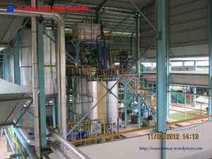 Oil Tank (COT) melalui Vibrating Screen double deck dengan mesh 20.
Dari COT Crude Oil dipompakan melewati Crude Oil Buffer Tank menuju Vertical Continuous Settling Tank (CST) kapasitas 120 m3. minyak mentah ditahan untuk pengendapan dalam CST untuk memisahkan minyak bagus dan sludge.
Kebutuhan air panas untuk proses klarifikasi dan pressing di suplay dari Hot Water Tank kapasitas 6 m3 dengan over flow menuju Hot Well Tank yang akan dipompakan kembali oleh Hot Well Pumps menuju Hot Well Tank.
Filed under: Clarification Station, Dasar Proses Pabrik, Palm Oil Mill | Tagged: 30 ton FFB per hour, Clarification, Clarification Station, Palm oil mill | Leave a comment »
Posted on April 14, 2012 by ivanemmoy
Quantity : One (1) unit.
Capacity : Two (2) units’ tankers’ at any time.
Construction :
” Steel structure column fabricated from IWF 200 x 100 mm.
” Provided with tie beam of IWF 150 x 75 mm.
” Span fabricated from 125 x 75 x 20 3.2 mm lips channel c/w dia. 12 mm sag
rods.
” Alu zine 0.5 mm thick used for roofing.
” Provided with operation platform, with 5 mm thick m.s chequered plate c/w 1″ x 1ᄐ” dia. Black steel pipe hand rail.
” Footing foundation of reinforced concrete mix K 225 c/w ground beam 20/30.
” Floor would be constructed with a 150 thick casted concrete reinforced with
two (2) layer of BRC M-6.
” Provided with two (2) no’s 6″ dia. discharge pipe c/w valve.
Dimension : 6.000 mm wide x 8.000 mm length floor area.

Filed under: Clarification Station, Palm Oil Mill | Tagged: 30 ton FFB per hour, Clarification, Despatch Sheed, Oil Storage, Palm oil mill | Leave a comment »
Posted on April 14, 2012 by ivanemmoy
Quantity :Two (2) units’.
Type : Rotary vane, Positive displacement.
Capacity : 50 tons/hour
Total head : 20 m
Pump speed : 500 rpm
Casing : Cast iron.
Rotor : Stainless steel.
Shaft : Stainless steel.
Seal : Mechanical, ball bearing construction.
Vane : Self adjusting for wear sliding.
Unit drive : Driven by 7,5 kW/ 10 Hp electromotor Teco, Electrim or equivalent through pulley and v-belt.
Accessories :
• A remote control valve.
• A return line pipe c/w valves and fittings to the clarification station.
Make :
• Blackmer or equivalent
• Oil collected below screen 3 mm thick of m.s plate would be provided and
discharge oil to crude oil tank.

Filed under: Clarification Station, Palm Oil Mill | Tagged: 30 ton FFB per hour, Clarification, Despatch Oil Pump, Oil Storage, Palm oil mill | Leave a comment »
Posted on April 14, 2012 by ivanemmoy
2 units of palm oil storage tanks of mild steel welded construction will be constructed.
Capacity : 2 x 2,000 tons of CPO.
Dimension : Ø 17,466mm I/D x 10,062mm H.
Bottom plate : 10 mm m.s. plate.
Shell plate : 1st course 9mm. m.s. plate.
: 2nd course 9mm. m.s. plate.
: 3rd course 8mm. m.s. plate
: 4th course 8mm. m.s. plate
: 5th course 6mm. m.s. plate
: 6th course 6mm. m.s. plate
• Bottom slope to a center sump from which oil is pumped and bottom drained.
• One of tank fitted with external spiral access ladder.
• Provided with internal ladder.
• Interconnecting catwalk between tank of 600mm wide c/w dia. 1” and 1¼” black pipe hand rail would be provided.
• Provided with 500mm dia. Roof manhole with cover.
• Roof perimeter c/w handrail all round.
• One unit 600mm diameter side manhole at first stage.
• One unit 6” dia. Vent pipe at to of dome.
• On sounding pipe c/w float Stainless steel and external level indicator.
• Scale level will be including with Metrology certificate.
Roof plate : 5mm thick m.s. plate.
Accessories :
• Ø 2″ indirect steam heating coils + 8 blank flanges.
• Ø 3″ palm oil inlet valve & Ø 4″ outlet valve (body cast steel, shaft
• and seat stainless steel).
• Steam valve and steam trap FT ball float type Spirax Sarco for
• heating coils + thermostatic control.
• Level indicator.
• Drain pipe Ø 2.5″
• Thermometer 150mm dia.
• Recycling pipe to clarification, with sight glass.

Filed under: Clarification Station, Palm Oil Mill | Tagged: 30 ton FFB per hour, Clarification, Oil Storage, Palm oil mill, Storage Tank | Leave a comment »
Posted on April 14, 2012 by ivanemmoy
Quantity : One (1)
Function :Suitable to support the entire clarification tank and vacuum drier.
Construction :
Main structure of IWF 200x100x21.33 kg/m mild steel H beam column. Supported with 200 mm, 150 mm m.s channel Braced with 75x75x6 mm mild steel handle bar Fitted with maintenance platform and covered with 5 mm thick mild steel chequered plate c/w dia. 1” and ¼” black steel handrail. Provided with
access ladders and interconnected walkways. One (1) runway beam c/w three (3) tons chain block would be fitted above sludge separator center line.
Filed under: Clarification Station, Palm Oil Mill | Tagged: 30 ton FFB per hour, Clarification, Clarification Structure, Palm oil mill | Leave a comment »
Posted on April 14, 2012 by ivanemmoy
Quantity : Two (2) units’.
Type : Centrifugal, Wear resistant.
Capacity : 40 m³/hour.
Total head : 30 m
Construction :
• Casing : Stainless steel
• Shaft : Stainless steel
• Impeller : Stainless steel
• Seal : Mechanical
Unit drive : 11 kW/ 15 Hp Teco, Electrim electromotor through pulley and v-belts.
Accessories :
• Discharge pipe to cooling tower 4” dia. Steam pipe sch. 80.
• A selector control switch Non return valve.
Make : Roto Pump, Kew Pump or equivalent
Size : 4” / 3”
Power : 15 Hp

Filed under: Clarification Station, Palm Oil Mill | Tagged: 30 ton FFB per hour, Clarification, Final Effluent Pump, Palm oil mill | Leave a comment »
Posted on April 14, 2012 by ivanemmoy
1 (one) unit Fat Pit, 3 compartment (1 for suction pump ; 1 for sludge and 1 for condensate sterilizer) below ground level, will be provided and installed to receive sludge centrifuges and condensate sterilizer.
Pump will be self priming with tank and lay on ground position.
Type : Rectangular 3 (three) compartment under ground
Construction : Concrete.
• 1 compartment for pump 1.5m x 6.6m to install roofing 2m height.
• Provided round pit 40mm dia. black pipe hand rail.
Capacity : 60 m³
Dimension : 6.6m x 6.1m x 1.5m.
Accessories : A float switches control. Shelter with spandex 0.5 mm.

Filed under: Clarification Station, Palm Oil Mill | Tagged: 30 ton FFB per hour, Clarification, Palm oil mill, Sludge Pit | Leave a comment »
Posted on April 14, 2012 by ivanemmoy
Quantity : Two (2) units’, one (1) unit as standby.
Type : Centrifugal.
Make : Kew or equivalent.
Capacity : 30 m³/hour
Total head : 30 m
Construction :
Casing Stainless steel, Shaft Stainless steel, Impeller Stainless steel, Seal Mechanical, Unit drive 4 kW/ 5.5 Hp Teco, Electrim electromotor through pulley
and V-belts,
Accessories A selector control switch & Non return valve.

Filed under: Clarification Station, Palm Oil Mill | Tagged: 30 ton FFB per hour, Clarification, Palm oil mill, Sludge Drain Pump | Leave a comment »
Posted on April 14, 2012 by ivanemmoy
Quantity : One (1) unit.
Type : Steel tank rectangular section.
Capacity : 18 m³
Construction :
The tank would be slope bottom construction Fabricated from 6 mm thick m.s plate of welded construction with m.s channel stiffeners. Tank divided by two (2) compartment Fitted adjustable oil skimming device, for draining skimmed oil into an oil tank for pumping back to the continuous settling.

Filed under: Clarification Station, Palm Oil Mill | Tagged: 30 ton FFB per hour, Clarification, Palm oil mill, Sludge Drain Tank | Leave a comment »
Posted on April 14, 2012 by ivanemmoy
Quantity : Two (2) units’.
Type : Centrifugal.
Capacity : 20m³ per hour, each.
Total head : 30 m
Speed : 1.450 rpm
Construction :
Casings Cast iron, Impeller Bronze, Shaft Stainless steel, Seal Mechanical, Unit
drive Direct coupling 5,5 kW/ 7,5 Hp Teco, Electrim electromotor on common
base plate and Allen Gwynnes pump.

Filed under: Clarification Station, Palm Oil Mill | Tagged: 30 ton FFB per hour, Clarification, Hot Well Pumps, Palm oil mill | Leave a comment »


 Oil Tank (COT) melalui Vibrating Screen double deck dengan mesh 20.


