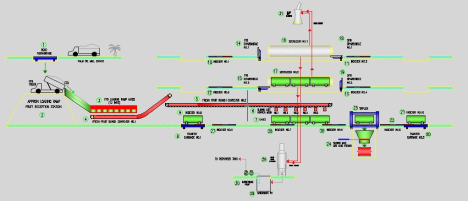
Flow Diagram Indexer System
I. STASIUN LOADING RAMP
1. Loading Ramp (12-doors) Hydraulics Systems
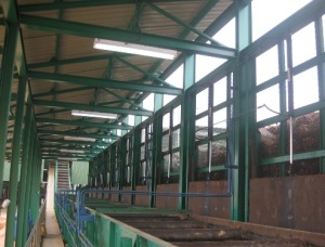
12 Doors Loading Ramp
Each lot consist of :
- 5kW Vickers Hydraulic Power Unit Twin Systems (160 liter) c/w valves and accessories
- 6 Nos Vickers Hydraulic manual control valve (Part # CM11N02R15-DDE-21)
- 12 Nos Vickers Hydraulic cylinders (Bore 63 x Rod 35 x Stroke 914mm stroke cylinder)
- 1 lot of connecting materials for 12doors site installation
- 1 No of Starter Panel for 2×5.5kW (Incoming wiring not included)
2. FFB Conveyor #2, 5 x Hopper Door (Feeding).
Hopper feedeng for 3 Cages Feeding (each Cage with 2 Hopper Door) – Last Door always open 5 x Hopper door mec structures
5 x Hopper Door Hydraulic Systems, consist of:
- 4kW (or 5.5 HP) Vickers Hydraulic Power Unit (80 liter) c/w valves and accessories
- 5 Nos Vickers Hydraulic manual control valve (Part # CM11-N02-R15-DE-21)
- 5 Nos Vickers Hydraulic cylinder (Bore 63 x Rod 35 x Stroke 914mm stroke cylinder)
- 1 lot of connecting materials for 5-doors site installation
- 1 No of Starter Panel for 4Kw

FFB Hooper Door
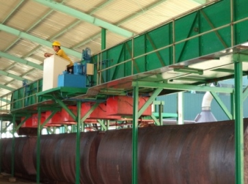
3. Intermediate And FFB Feeding Line Indexer.
Indexer #7 & #8: Indexer Structure c/w frame; roller and pulling pad. a) One indexer at Feeding Line to push loaded cages to Dry End Transfer Carriage. Movable trolley with pulling and pushing pad sitting on it
FFB Feeding Line Indexer Hydraulic Systems
Each lot consist of:
- 15kW (or 20HP) Vickers Hydraulic Power Unit (250 liter) c/w valves and accessories
- 1 No Vickers hydraulic cylinders (Bore 100 x Rod 70 x Stroke 2100mm stroke cylinder)
- 1 lot of connecting materials for installation
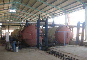
II. STATION STERILIZERS
Criteria as following…Sterilizer 30ton (2x15t FFB Cage), sterilizer door 3200mm; Dished End body & Insulation). Each sterilizer door has two door lock/unlock cylinders bracket provided by Door OEM and a door open/close cylinderbracket
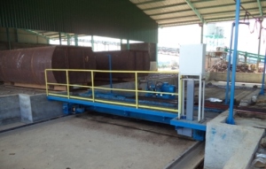
1. Transfer Carriage (Dry End & Wet End)
10-ton Transfer Carriage Structure (Rotary Lock; Sprocket (Drive and Driven); Wheels a) Transfer carriage length 6.8m, width 1.6 meter, height 1m, 2 pillar block with wheels driven by hydraulisc, with hydraulics driven rotary lock. 2 sets of rotary lock structure, bumper hump to align transfer carriage structure while loading and unloading cage. b) Indexer structure c/w frame; roller and pulling pad. (Indexer TC #1 & TC#2)
Hydraulic Group TC : 10-ton Transfer Carriage (Indexer, Rotary Lock n Travelling) Hydraulics Systems
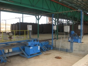
Dry End Transfer Carriage
Each lot consist of:
- 15kW Vickers Hydraulic Power Unit (160 liter) c/w valves and accessories
- 2 Nos. Char-Lynn Hydraulic motors for travelling drive (Part #: 112-1068-006)
- 2 Nos. Char-Lynn Hydraulic motors for rotary lock – self-aligning locking mechaniniscm (Part # 112-1068-006)
- 2 Nos Vickers hydraulic cylinders (Bore 100 x Rod 70 x Stroke 2100mm stroke cylinder)
- 1 lot of connecting materials for installation
Wet End Transfer Carriage
2. FFB Bay (Dry End) Drawbridge And Indexer.
Drawbridge 3.6 meter length w/ Drawbridge structure, base plate sitting double pillar block for trunnion drawbridge. Indexer Structure (#1; #3) at FFB Bay c/w frame; roller and pulling pad at dry end to push Cages into each Steriliser (FFB Bay) Movable trolley with pushing pad siiting into it. Base plate for trunnioin mounting included.
Hyd Grouping: Single HPU to be shared by 2 x Sterilizer Doors; 2 x Drawbridge and 2 x Indexer (facing Sterilizer) Hydraulic Systems

FFB BAY (DRY END) DRAWBRIDGE AND INDEXER
Each lot would consist of:
- 15kW (or 20 HP) Vickers Hydraulic Power Unit (250 ltr) c/w valves and accessories
- 2 Nos. Vickers hydraulic cylinders for 2 x Door opening/closing (Bore 100 x Rod 70 x Stroke 540*mm stroke cylinder)
- 4 Nos.Vickers hydraulic cylinders for 2 x Door locking/locking (Bore 80 x Rod 50 x Stroke 225*mm stroke cylinder)
- 2 Nos. Vickes hydraulic cylinders for 2 x Drawbridge (Bore 100 x Rod 70 x Stroke 657mm stroke cylinder)
- 2 Nos Vickers hydraulic cylinders for 2 x Indexers (Bore 100 x Rod 70 x Stroke 2100mm stroke cylinder)
- = final cylinder stroke to suit specs of St Door OEM chosen
- 1 lot of connecting materials for installation
3. SFB Bay (Wet End) Drawbridge And Indexer.
Drawbridge 3.6 meter length w/ Drawbridge structure, base plate sitting double pillar block for trunnion drawbridge. Indexer Structure (#2; #4) at SFB Bay c/w frame, roller and pulling pad to push Cages out of Sterilizers (SFB Bay). Movable trolley with pushing pad siiting into i. Base plate for trunnioin mounting included.
Hyd Grouping: Single HPU to be shared by 2 x Sterilizer Doors; 2 x Drawbridge and 2 x Indexer (facing Sterilizer) Hydraulic Systems
SFB BAY WET END DRAWBRIDGE AND INDEXER
Each lot would consist of:
- 15kW (or 20 HP) Vickers Hydraulic Power Unit (250 ltr) c/w valves and accessories
- 2 Nos. Vickers hydraulic cylinders for 2 x Door opening/closing (Bore 100 x Rod 70 x Stroke 540*mm stroke cylinder)
- 4 Nos.Vickers hydraulic cylinders for 2 x Door locking/locking (Bore 80 x Rod 50 x Stroke 225*mm stroke cylinder)
- 2 Nos. Vickes hydraulic cylinders for 2 x Drawbridge (Bore 100 x Rod 70 x Stroke 657mm stroke cylinder)
- 2 Nos Vickers hydraulic cylinders for 2 x Indexers (Bore 100 x Rod 70 x Stroke 2100mm stroke cylinder)
- = final cylinder stroke to suit specs of St Door OEM chosen
- All cylinders in SFB Bay are using stainless steel barrel and rod
- 1 lot of connecting materials for installation
4. Before And After Tippler Indexer.
Single HPU to be shared by two indexers (Indexer # 5 and #6)
- Indexer #5: Indexer Structure c/w frame; roller and pulling pad. indexer Before Tipper to push loaded cage precisely to Tipper. Movable trolley with pushing pad sitting on it.
- Indexer #6: Indexer Structure c/w frame; roller and pulling pad. indexer After Tipper to push cage to Feeding Line. Movable trolley with pulling and pushing pad sitting on it.
Hydraulic Grouping : 2 Indexers Hydraulics Systems
Tippler Indexer
Each lot consist of:
- 15kW (or 20HP) Vickers Hydraulic Power Unit (250 liter) valves and accessories
- 2 Nos Vickers hydraulic cylinders for 2 x Indexers (Bore 100 x Rod 70 x Stroke2100mm stroke cylinder)
- 1 lot of connecting materials for installation
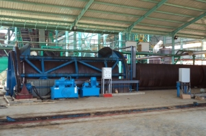
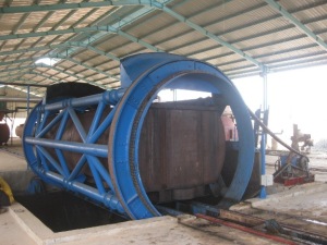
5. Cage Tippler.
10-ton Cage Tipper with Diameter 3.3mm, length 6.5m with fixed based roller for tipper web plate 32mm to sit. Well engineering designed steel structured to ensure light weight and rigid feature. Tipper capable of rotating the single Cage with full SFB inside Cage without vibration. Counterweight is installed to ensure smooth downturn. Calculation provided. Scope of supply complete with accessories as stated in drawing provided (tensioner; tipper chain), inclusive of Hydraulics Drive Foot bracket adn Drive Coupling.
10-ton Tipper & SFB hopper Autofeeder Hydraulic Systems
TIPPLER
Each lot consist of :
- 15kW VickersHydraulic Power Unit (twin pump systems) c/w valves and accessories c/w valves and accessories
- 1 Nos Vickers Hydraulic motor + reducer (Part # GM54BZD120221)
- 1 Nos Vickers Hydraulic cylinder M3000-25-1200
- 1 lot of connecting materials for installation
6. Indexer Trench and Rail Track
- Sterilizer line indexer trench (length 2x33m) consist of Indexer Trench (UNP150x75)
- Tipper and Feeding line indexer trench (length 2x52m) consist of Indexer Trench (UNP150x75)
III. Automation & Control
1. Electrical and Control Integration Works and Automation
Control Stations for Indexer Systems: Eaton proposed design comes with Feeder Panel (Qty: 1 Lot); Individual Remote Consoles (Qty: 5 Sets), to be located on-top catwalk platform and Panels for Remote IOs, to be located on the ground. Feeder Paenl is proposed to be located in Control Room together with Sterilizer Automation Panel. Each Remote Console is solid floor standing type and equipped with MIMIC diagram showing the operations on relevant equipments for Auto / Manual Control. Local Panel for each Transfer Carriage provide. Principle of design is based on Distributed Control and running on Eaton SmartWire-DT commmunication.
PANEL FEEDER WITH PLC AUTOMATION
2. Feeder Panel with Starter (in CONTROL ROOM)
2.1. Transfer Carriage.
Remote Console #4 (RC4) : Auto and Manual for Transfer Carriage (TC#1), Indexers (#1) (FFB Bay or Dry End). and Indexers (#9) (intermediate and feeding) Eaton XV102 Series HMI/PLC as Controller with high speed algorithm and high level of visibility for efficient operation, which is with IEC-61131 CoDeSys language.• Eaton Remote I/O Systems.• c/w Main Junction Box and various lots of Junction Boxes for cable termination to all solenoid valves and proximity sensors for Tranfer Carriage and Indexers • !P69K Proximity sensors with sensor clamp for all.
Local Panel (LP) : HPU Starter and Local operation ofTransfer Carriage (TC#2)
2.2. Sterilizer Doors, Drawbridges & Indexer.
Remote Console #1 (RC1) : Auto and Manual for Sterilizer Doors & Drawbridges & Indexers (#2 and #4) Control (FFB Bay or Dry End). Eaton XV102 Series HMI/PLC as Controller with high speed algorithm and high level of visibility for efficient operation, which is with IEC-61131 CoDeSys language.• Eaton SmartWire-DT Remote I/O Systems.• c/w Main Junction Box and various lots of Junction Boxes for cable termination to all solenoid valves and proximity sensors for Sterilizer Doors; Drawbridges; and Indexers • Pressure transmitters c/w siphon tube for each Sterilizer end • Photo sensors of Cage of Drawbridge for each of the Drawbridge • IP69K Proximity sensors with sensor clamp for all. •Tell tale – purge valve from Alfa Hi-Flow (country of origin Australia) Ball Valve. Model 2012, DN40 (1.5”), 1000 psi, 3-piece body, F/Bore, BW Ends, SS316 Body and Trim, PTFE (max 200 degree C) Seats c/w ITQ Electric Actuator, model ITQ-0080 (220v/1Phs/50Hz), On/Off operaton c/w standard specification.This tell tale valve is installed at the Sterilizer Door outlet port
Remote Console #2 (RC2) : Auto and Manual for Sterilizer Doors & Drawbridges & Indexers (#3 and #5) Control (SFB Bay or Wet End). Eaton XV102 Series HMI/PLC as Controller with high speed algorithm and high level of visibility for efficient operation, which is with IEC-61131 CoDeSys language.• Eaton SmartWire-DT Remote I/O Systems.• c/w Main Junction Box and various lots of Junction Boxes for cable termination to all solenoid valves and proximity sensors for Sterilizer Doors; Drawbridges; and Indexers • Pressure transmitters c/w siphon tube for each Sterilizer end • Photo sensors of Cage of Drawbridge for each of the Drawbridge • !P69K Proximity sensors with sensor clamp for all. •Tell tale – purge valve from Alfa Hi-Flow (country of origin Australia) Ball Valve. Model 2012, DN40 (1.5”), 1000 psi, 3-piece body, F/Bore, BW Ends, SS316 Body and Trim, PTFE (max 200 degree C) Seats c/w ITQ Electric Actuator, model ITQ-0080 (220v/1Phs/50Hz), On/Off operaton c/w standard specification.This tell tale valve is installed at the Sterilizer Door outlet port
2.3. Tippler.
Remote Console #3 (RC3) : Auto and Manual for Cage Tipper c/w SFB Hopper Door & Before and After Tipper Indexers (#6 and #7). Eaton XV102 Series HMI/PLC as Controller with high speed algorithm and high level of visibility for efficient operation, which is with IEC-61131 CoDeSys language.• Eaton SmartWire-DTSystems.• c/w Main Junction Box and various lots of Junction Boxes for cable termination to all solenoid valves and proximity sensors for Tipper and Indexers • IP69K Proximity sensors with sensor clamp for all.
3. Eaton Sterilizer Automation.
One (1) set of panel sterilizer automation interlocked with Sterilizer Doors for Indexing Systems. Panel design w/ MIMIC is for 2 Sterilizers, with Eaton Galileo SCADA; Eaton XV152 Series HMI/PLC, IP65 rating, (10.4”) catered for 2 x Sterilizers with Microsoft CE Operating Systems; or efficient operation, which is with IEC-61131 CoDeSys language.
Main Control Board together with proximity switches, pressure transmitter, and cabling systems.
Sterilizer Control Systems are for automation 3 Steam Valves sequencing per Sterilizer. 10 different programs possible.
- Inlet: 8” High Performance Butterfly Valve with Metal Seat c/w ON/Off type Pneumatic Actuator with Auto Declutchable Manual Override Handwheel and Mounting Bracket & Adaptor with matching flanges, bolts, nuts, washer and Gasket
- Exhaust: 8” High Performance Butterfly Valve with Metal Seat c/w ON/Off type Pneumatic Actuator with Auto Declutchable Manual Override Handwheel and Mounting Bracket & Adaptor with matching flanges, bolts, nuts, washer and Gasket
- Condensate: 8” High Performance Butterfly Valve with Metal Seat c/w ON/Off type Pneumatic Actuator with Auto Declutchable Manual Override Handwheel and Mounting Bracket & Adaptor with matching flanges, bolts, nuts, washer and Gasket.
4. Eaton Automatic Back Pressure Control Panel
One set of BPV control panel c/w HMI/PLC Operator’s interface and pressure transmitter and pressure switchfor BP Vessel with standard accessories. High presure rating, low limit pressure switch. Cables, cable tray, conduits from BPC Panel to Valves. Include following Valves for Back Pressure Receiver :
- 3” Globe Control Valve c/w Pneumatic Actuator (Positioner) a delta-P of approximately 29 Bar with positional controls (4-20mA). – Full Modulating Valve, Mounting Bracket & Adaptor with matching flanges, bolts, nuts, washer and Gasket. (Steam Make Up).
- 6 ” High Performance Butterfly Valve with Metal Seat c/w ON/Off type Pneumatic Actuator with Auto Declutchable Manual Override Handwheel and Mounting Bracket & Adaptor with matching flanges, bolts, nuts, washer and Gasket. Flange: JIS10K / PN16 (Steam Exhaust or Surplus Valve).
Filed under: Automation, Fruit Reception, Sterilizer Station, Threshing Station | Tagged: cylinder hydraulic, eaton, Horizontal Sterilizer, Hydraulic Power Unit, indexer, indexer system, vickers | 2 Comments »